
Click Here To Preview Online
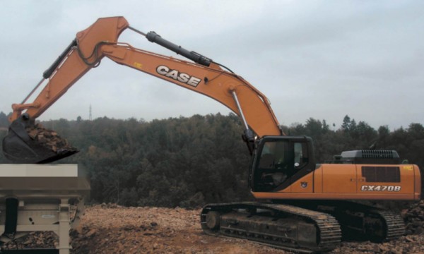
Recommendation of instruction CASE CX470B CRAWLER EXCAVATOR Service Repair Manual
The most important feature of this manual is its professionalism. The manual objectively introduces and scientifically explains the contents of the product, so as to understand the characteristics of the product, master the operation procedures of the product, and know how to repair the CASE CX470B CRAWLER EXCAVATOR. The content of this manual is perfect, not like an instruction book, but more like a textbook. The new knowledge, new technology and graphic interpretation contained in it also play a role in spreading knowledge.
CASE CX470B CRAWLER EXCAVATOR Service Repair Manual is divided by illustrations to show you the detailed structure and functions of the CASE CX470B CRAWLER EXCAVATOR. The illustrations are clean and tidy, and its full of details. And the text at the bottom is also explained with the illustrations, which makes the whole display more stereoscopic.
Through the introduction of the above, I’m sure you can feel that this CASE CX470B CRAWLER EXCAVATOR Service Repair Manual is both an illustrative introduction to the product and its main functions. It is practical, objective and accurate to reflect the product. Guidance includes the knowledge and form diversity of guiding consumers to use and maintain the product. The expression form is in the form of text, as well as tables, pictures and photos. I believe that as long as you have CASE CX470B CRAWLER EXCAVATOR Service Repair manual, you can understand the performance, components and maintenance of this CASE CX470B CRAWLER EXCAVATOR, because this manual is really succinct but not simple, the content is substantial but not complicated. It is a real service for customers. This manual is enough about this skid steer loader.
Service Repair Manual Covers:
1 GENERAL INFORMATION
Safety, general information and standard torque data
General specifications and special torque setting
2 ENGINE
Removal and installation of the engine
Removal and installation of the fuel cooler, engine inter-cooler,
radiator and oil cooler
Removal and installation of the turbo charger
Removal and installation of EGR cooler and EGR valve
Removal and installation of the engine hood
Engine specifications
Disassembly and assembly of the engine
3 FUEL SYSTEM
Removal and installation of the fuel tank
Removal and installation of the supply pump and common rail
Removal and installation of the injectors
Fuel engine system
4 ELECTRICAL SYSTEM
Service connector kit
Electrical and engine functions and service support
Removal and installation of the starter motor
Removal and installation of the alternator
Electrical equipment & electrical circuit diagrams
Engine error code (DTC)
Main body error code (DTC)
Troubleshooting, 6UZ1 engine
5 UNDERCARRIAGE
Removal and installation of tracks
Rollers
Take-up roller
6 DRIVE TRAIN
Removal and installation of the drive motor and final drive transmission
Disassembly and assembly of the drive motor and final drive transmission
Removal and installation of the swing motor and swing reduction gear
Disassembly and assembly of the swing reduction gear
7 UNDERCARRIAGE HYDRAULICS
8 UPPERSTRUCTURE HYDRAULICS
Specifications, troubleshooting, checks and hydraulic pressure settings
Removal and installation of the hydraulic reservoir
Removal and installation of the main hydraulic pump
Removal and installation of the main hydraulic control valve
Removal and installation of the attachment cylinders
Removal and installation of the hydraulic swivel
Removal and installation of the pilot blocs
Disassembly and assembly of the main hydraulic pump
Disassembly and assembly of the main hydraulic control valve
Disassembly and assembly of the attachment cylinders
Disassembly and assembly of the hand control levers
Disassembly and assembly of the foot control levers
Disassembly and assembly of the cushion valve
Removal and installation of the safety valve
Disassembly and assembly of the swing motor
Hydraulic functions
Hydraulic component functions
9 UPPERSTRUCTURE
Removal and installation of the counterweight
Removal and installation of the boom, dipper and bucket
Removal and installation of the seat
Removal and installation of the cab and cab equipment
Air conditioner functions and troubleshooting
Air conditioning unit
Air conditioning components
Large size hydraulic schematics
Large size electrical schematics
Product details:
File Format: PDF
Language: English
Manual Type: Service Repair Workshop Manual
Compatible: All Versions of Windows & Mac, Android, Linux
Download immediately after payment.
Have any questions. Please write to us.
Our support email: ebooklibonline@outlook.com